Vhdl Code For Not Gate

Home vhdl logic gates not gate.
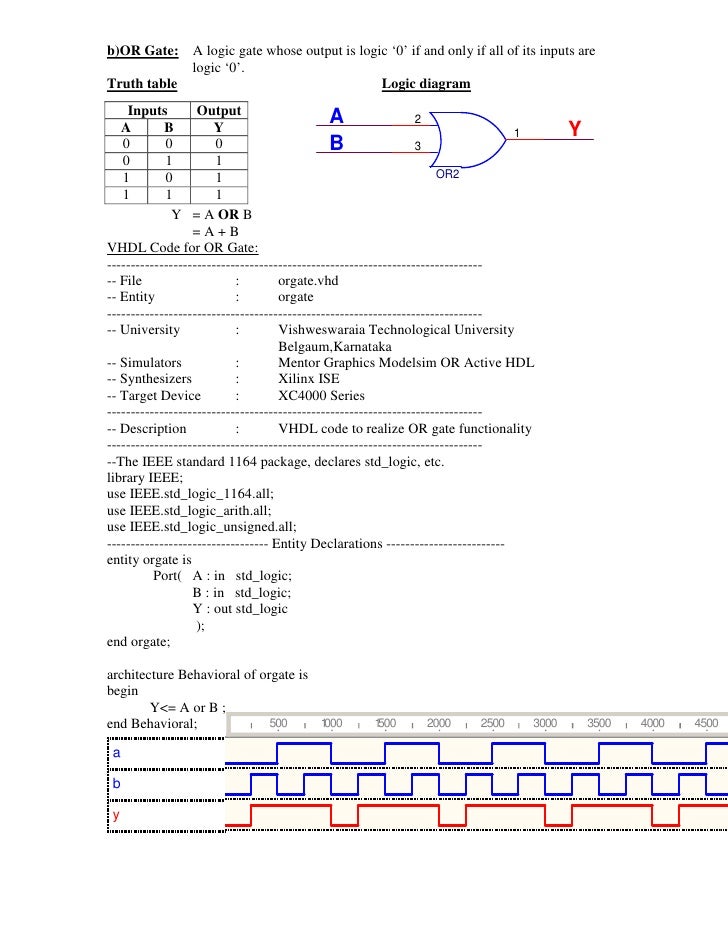
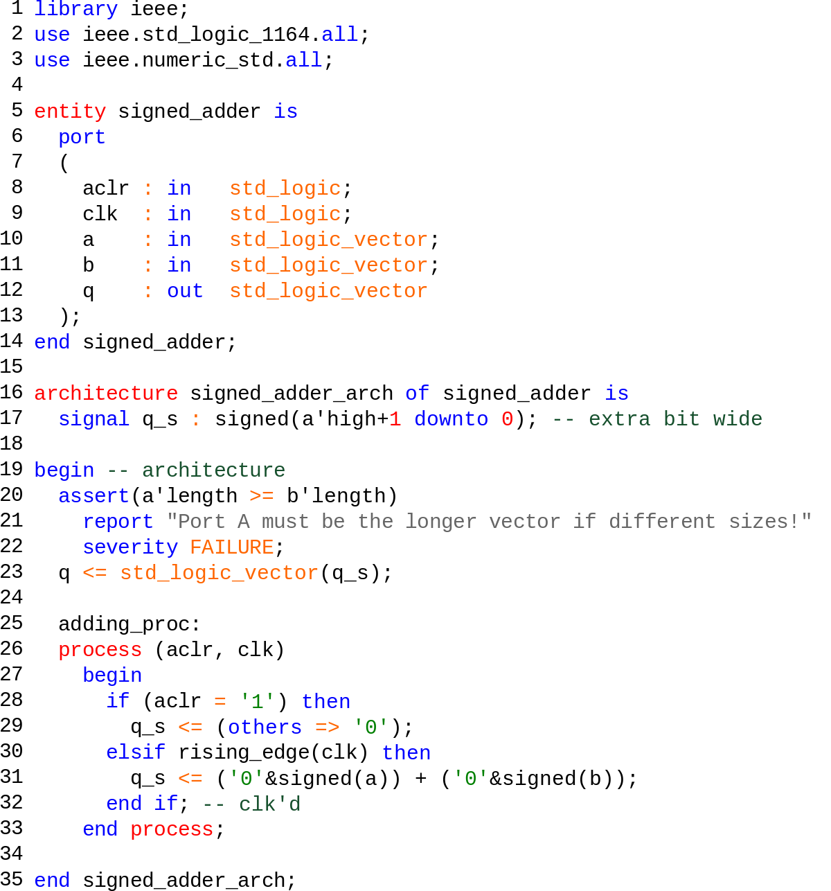
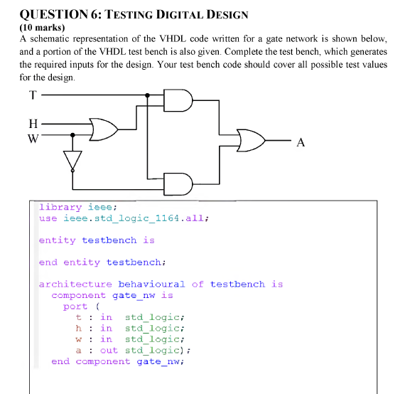
Vhdl code for not gate. The statements do not run sequentially from top to bottom but rather in parallel. Vhdl basic or gate. In this post we will take a look at implementing the vhdl code for all logic gates using dataflow architecture first we will take a look at the logic equations of all the gates and then the syntax. Nor gate with truth table and vhdl.
Module not gate level output y input a. Nand and nor logic gates in vhdl nand gate. Proj 44 orthogonal code. Vhdl code for full adder with test benchthe full adder circuit adds three one bit binary numbers c a b and outputs two one bit binary numbers a sum s and a carry c1.
The compensation code could therefore be put above the gate implementation or below it. The full adder is usually a component in a cascade of adders which add 8 16 32 etc. The not gate can be implemented using the data flow modelling or the behavioural modelling. The code does not first run the and gate part and then the or gate part.
This style of modeling for nor gate use the behavior algorithm to describe the operation. You may wish to save your code first. Nand and nor vhdl project. Validate your account not supported during collaboration.
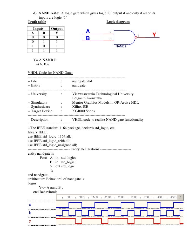
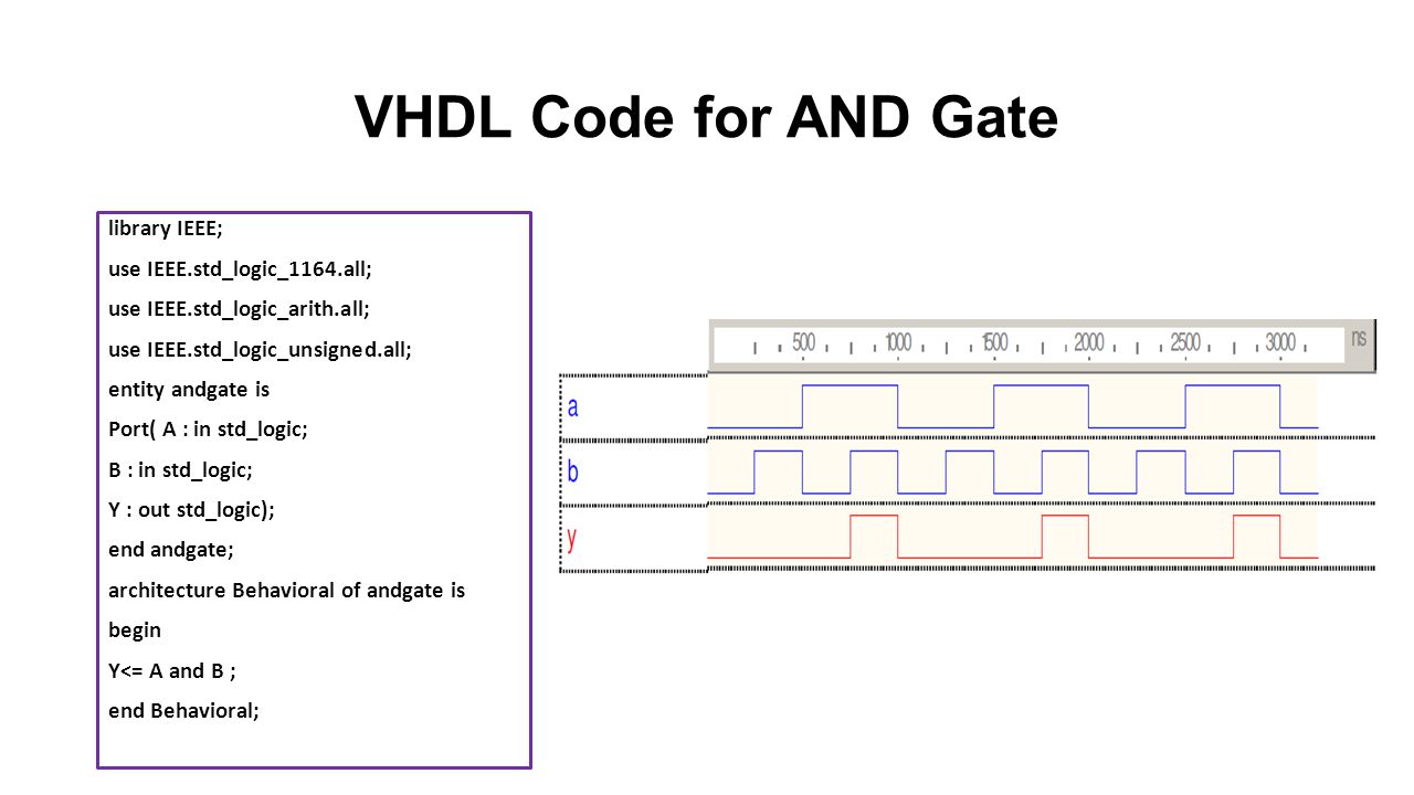
Vhdl code for and gate using modelsim how to use modelsim. The vhdl nand keyword is used to create a nand gate. The vhdl nor keyword is used to create a nor gate. Verilog code for not gate using gate level modeling we begin the hardware description for the not gate as follows.
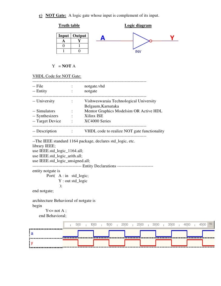
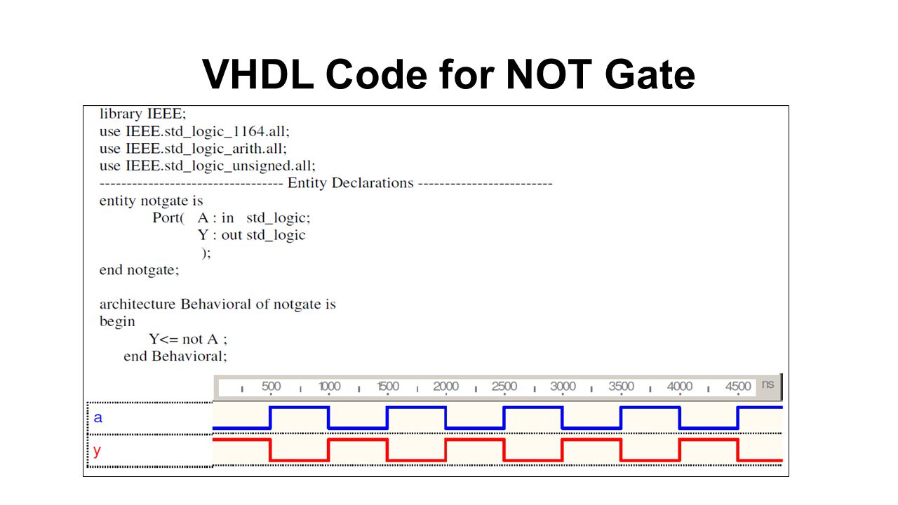
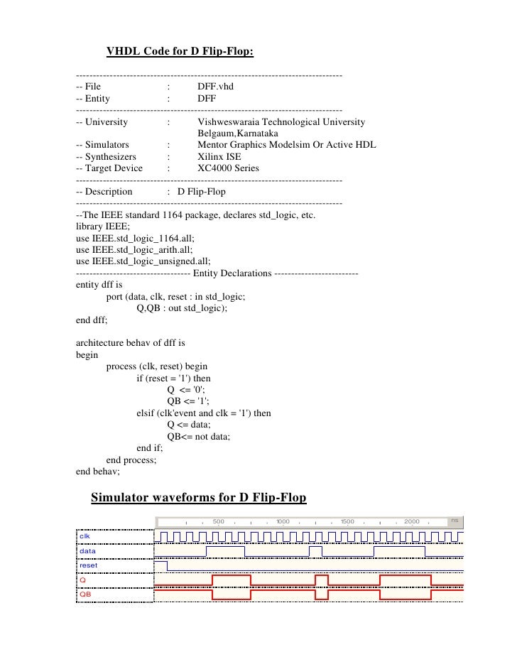
Below code can implement not gate in vhdl. In data flow modelling of not gate the operator not is used to logically invert the input a. To encourage development of these features for collaboration tweet to edaplayground. Nand gate with truth table and vhdl.
For a nor gate the output is high when both a and b are low 0 otherwise the output is high 1 vhdl code for synthesizing nor gate. Logic gates are the building blocks of digital electronics digital electronics employ boolean logic. Creating deleting and renaming files is not supported during collaboration. The above code demonstrates concurrency in vhdl.
The code is written in data flow model. Figure below shows the symbol and the truth table of the not gate. The and and or gates also run in parallel. In verilog hdl we define the module using module a basic building block.
This code listing shows the nand and nor gates implemented in the same vhdl code.

